


Control - transmitter NRF24L01
How do you program the yacht's control system? We used Arduino nano and NRF24L01 module. We share the transmitter code for RC yacht model with two servo motors.
5/11/20262 min read
We at RC Sailing chose the well-known Arduino Nano for our setup, both on the transmitter/controller side and on the yacht/receiver side.
However, nothing prevents us from using other microcontrollers such as ESP32, Raspberry Pi Pico, STM32, and many others.
To begin our adventure with programming remote-controlled models, we need a development environment. In our case, this is Arduino IDE, which can be downloaded for free from the manufacturer's website: arduino.cc/en/software/
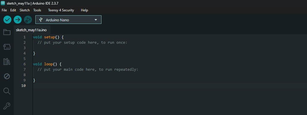
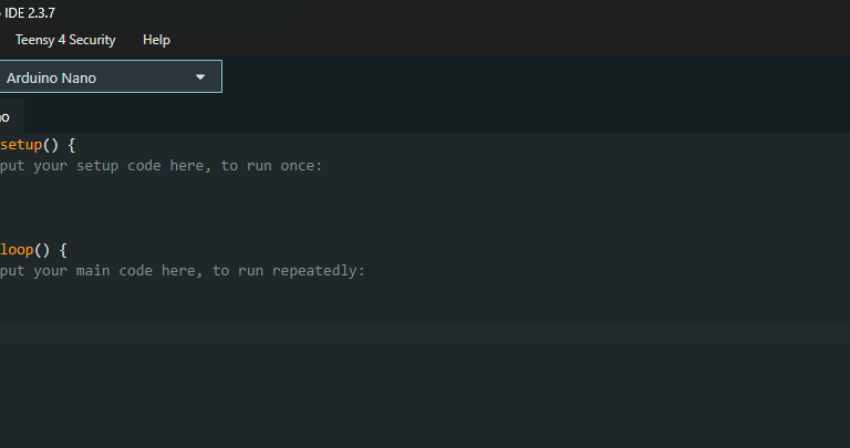
After opening the program, we need to create a new sketch, which should look like the one shown in the title image. Following the descriptions in the image, we enter the code in the appropriate places - the code that the microcontroller should execute once, or the code that should run in a loop.
In addition, before "void setup" we need to include the libraries we want to use. In our case, this will certainly be the NRF24L01.h and RF24.h libraries. They contain predefined functions and settings related toi the radio module we have chosen.
At the beginning, we also need to define which microcontroller pins are responsible for which signals.
In the code below, we define pins D9 and D10 as CE and CSN, which are crucial for the operation of the radio module. A more detailed explenation can be found on the blog dedicated to the NRF24L01.
We also define the communication address between the transmitter and the receiver - any string will do, as long as it is the same on both the transmitter and receiver side.
We additionally define two analog inputs, thanks to which we can convert the signal from the joystick or potentiometer into a useful numeric value for controlling the yacht.
The code below is for the transmitter side, the receiver is discussed in the next article.
#include <SPI.h>
#include <nRF24L01.h>
#include <RF24.h>
#define CE_PIN 9
#define CSN_PIN 10
const byte slaveAddress[5] = "00001";
const byte JoyX = A1;
const byte JoyY = A2;
RF24 radio(CE_PIN, CSN_PIN); // Create a Radio
struct Data
{
int16_t x;
int16_t y;
};
Data dataToSend;
void setup() {
Serial.begin(9600);
Serial.println("SimpleTx Starting");
radio.begin();
radio.setDataRate( RF24_250KBPS );
radio.setRetries(3,5); // delay, count //radio.setRetries(3,5); // delay, count
radio.openWritingPipe(slaveAddress);
radio.stopListening();
}
void loop() {
send();
}
void send()
{
bool rslt;
int16_t Val1=map(analogRead(JoyX),0, 1023, 0, 120);
int16_t Val2=map(analogRead(JoyY),0, 1023, 0, 180);
dataToSend.x = Val1;
dataToSend.y = Val2;
rslt = radio.write( &dataToSend, sizeof(dataToSend) );
Serial.print("Joy X : ");
Serial.println(dataToSend.x);
Serial.print("Joy Y : ");
Serial.println(dataToSend.y);
if (rslt)
{
Serial.println(" Acknowledge received");
}
else
{
Serial.println(" Tx failed");
}
}
RC sailing
We invite you to connect with us on social media or by email or phone
Contact
+48 788 619 201
© 2024. All rights reserved.